Know Your Transformers Page 2
N Squared
We've just seen that if a transformer has a turns ratio (secondary/primary) of N, then the secondary voltage will be N times the primary voltage. As the transformer is a passive device and so cannot add signal power, the product of voltage times current (VI) must be the same in both the primary and secondary circuits (assuming here an ideal transformer with no internal losses). So a primary current of I becomes a secondary current of I/N. Let's take once again the simple example of a transformer with twice as many turns in its secondary as it does in its primary. If the primary voltage and current are V and I respectively, then the secondary voltage and current will be 2V and I/2.
 Let's apply Ohm's Law – voltage equals current times resistance (V = I x R) – to this example. If V/I = R in the primary circuit, then in the secondary circuit 2V/0.5I = 4R. So there has been an impedance transformation equal to N2 (or N x N).
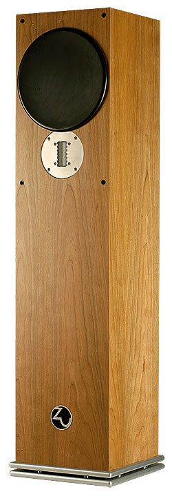
Perhaps the most extreme example of transformers being used for impedance matching in audio is in ribbon tweeters – by which I mean real ribbon tweeters, not the isodynamic tweeters that are so often mis-labelled as being 'ribbons'. In a genuine ribbon tweeter the ribbon is a thin, narrow strip of metal – usually aluminium as it desirably combines low density with high electrical conductivity – which not only serves as the signal conductor but is also the diaphragm that radiates the sound.
If we take the example an aluminium ribbon that's 60mm long, 10mm wide and 10µm (0.01mm) thick, it will have a resistance of 15.9 milliohms (0.0159 ohms) – way too low for a conventional audio amplifier to drive, to which the ribbon will appear to be a short-circuit. So conventionally a transformer is used to provide an impedance match between ribbon and amplifier. To raise the ribbon's apparent resistance to 8ohm in this example, we need a transformer with a turns ratio of about 22.4 (since 22.42 x 0.0159 = 7.98).
The other instance where transformer impedance matching is important in audio, as I've already alluded to, is in valve power amplifiers. Here the output transformer performs vital impedance matching in both directions. The loudspeaker impedance is stepped up to a value compatible with the valve output stage, and the high output impedance of the output stage is stepped down to a value which, ideally, is sufficiently low not to compromise electromagnetic damping of the loudspeaker too badly, or to affect frequency response too obviously as a result of the speaker having frequency-dependent impedance.
Balun Transformer
Most consumer audio equipment uses unbalanced interconnections: one wire carries signal, the other is connected to earth (see Fig 3a). In professional audio equipment interconnection is more normally balanced: the two wires carry the same signal but with opposing polarity (see Fig 3b).
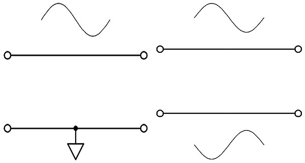
To be strictly accurate, what makes an interconnection balanced is actually that the two wires 'see' equal source resistance, not that they each carry signal. But most balanced audio connections carry, as depicted, twin signals in antiphase. The advantage of this is that external interference will induce equal, in-phase voltages in the two wires (a 'common mode' signal) which is rejected at the receiver, which extracts the difference between the voltages on the two signal wires (the 'differential mode' signal).
Sometimes there is a need to convert a balanced signal to an unbalanced signal or vice-versa, and this can be achieved using a 'balun' transformer, as shown in Figs 4a and 4b. These diagrams are deliberately simplistic to illustrate the essential idea; real application is more complex and, particularly in the case of balanced to unbalanced connection, will often have to account for a voltage mismatch between the balanced output and unbalanced input.
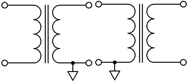
Readers interested in the details should download and read Jensen Transformers' application note AN-003, 'Interconnection of balanced and unbalanced equipment', which can be found at www.jensen-transformers.com/application-notes.
Due to the fact that the primary and secondary windings of a transformer are electrically separate (ignoring, once again, the special case of the autotransformer), a transformer provides galvanic isolation – separating the earth circuit of the equipment connected to its primary from the earth of that connected to its secondary.
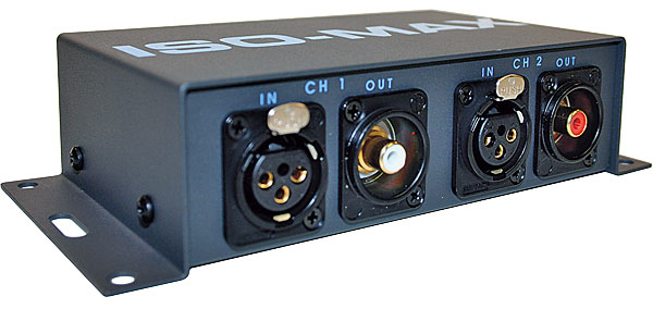
This is useful because earth currents are a cause of hum and buzz that can be difficult to diagnose and eliminate, particularly in complex audio set-ups. 'Hum eliminators' use transformers to provide galvanic isolation but need to be used with care because, particularly in cheaper examples, the transformers may not be of the highest quality, resulting in compromised fidelity.
In most hi-fi systems, even when using unbalanced connections, it should be possible to achieve acceptably low hum and buzz levels without resorting to 'hum busters'. But if they prove unavoidable, use premium quality items.
Autotransformer
Seeing as I've mentioned the autotransformer twice, the least I can do is give you a couple of examples of its use in audio despite, as I've said, it being a rarity. In fact I only know of two roles in which the autotransformer has been used.
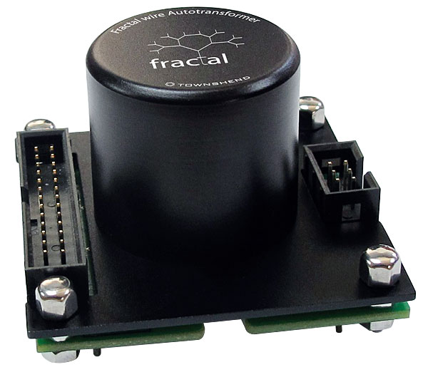
The first deals with production tolerances in drive unit sensitivity – an application of the autotransformer that was once popular with the BBC. Fig 5 shows an example, in the form of the crossover network developed for the LS3/5A. The autotransformer, component L3, has seven taps in total – two at either end and five intermediate – which allow the signal level to the tweeter (a KEF T27) to be adjusted in discrete steps relative to the bass-mid unit (which is a selected KEF B110). Once the appropriate autotransformer tap is established, capacitor C2 is chosen to achieve the desired high-pass corner frequency of the network.
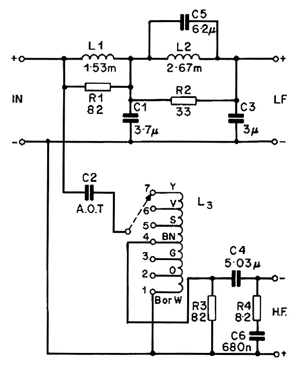
A great many more taps than this are used in the autotransformers that form the level control element in Townshend Audio's Allegri+ and Enigma preamplifiers, which have 24 and 72 attenuation steps respectively. I'm not aware of any other manufacturer using the autotransformer for volume control in this way, in place of the more usual variable potentiometer or stepped attenuator.
So Much More To Say
There is so much more to understand about transformers beyond this simple introduction. Important topics that haven't been touched on here include transformer bandwidth (transformers have response limitations at both high and low frequencies); transformer distortion (which is one of the main justifications for preferring electronic alternatives); and inter-winding capacitances which provide a direct path between the primary and secondary at high frequencies and may require incorporation of an electrostatic screen to control.
Other topics include the use of bifilar windings to cancel self-inductance; the magnetic performance of different core materials and geometries (E-I core, toroidal, etc); and the minimisation and screening of a transformer's radiated magnetic field, which is of particular concern when it comes to mains transformers.
If you want to understand transformers inside out, there's a lot more reading to do…


