Know Your Transformers
![]()
There isn't much in a modern hi-fi system that would be familiar to the great 19th century English physicist Michael Faraday. But a time-travelling Faraday – bemused by radio frequency communication, lasers and sound reproduction in general – would find something reassuringly familiar in the transformer. For it was he who first demonstrated that electromagnetic induction can be used to link one electrical circuit to another.
Most items of mains-powered audio equipment contain a mains transformer, and some other items – albeit fewer than five decades ago – contain signal transformers also, usually at their input or output. Transformers in analogue signal paths tend to be frowned upon today, with differential amplifiers used in preference. But the vast majority of valve (tube) power amplifiers have an output transformer – OTL (output transformerless) valve amps have always been an exotic rarity.
Splendid Isolation
At the opposite end of the size scale, transformers are often used in digital signal interfaces, such as S/PDIF, to provide galvanic isolation (ie, to separate the earth circuitry of sender and receiver) and to create a balanced interconnection that improves the rejection of external electromagnetic interference.
If you've encountered hum eliminators – which are used both domestically and professionally as a quick means of fixing earth loop issues – these too contain transformers, whose galvanic isolation prevents the flow of hum-inducing earth currents.
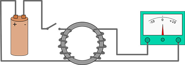
In other words, while transformers may not be nearly as ubiquitous as once they were in audio they are still around and still certainly important. And this means that every audiophile is better off knowing the essentials about them. Let's begin back with Faraday. What he showed in one of his famous demonstrations, which took place at the Royal Institution on the 29th of August 1831, was that if two otherwise separate wires were coiled around a toroid – a ring – of iron, with either end of one wire connected across a galvanometer and the ends of the other wire connected to a battery (see Fig 1, below left), then making or breaking the battery connection would cause the galvanometer needle in the other circuit to twitch in response. The needle would move in one direction as the battery connection was made, and in the other when the connection was broken. Somehow the change in electrical current flow in one circuit was reflected in a change in current flow in the other.
Core Values
What Faraday had discovered was the phenomenon of electromagnetic induction, on which all transformers depend. The change in current in the first circuit – known in transformer parlance as the primary – caused a change in magnetisation of the iron ring (transformer terminology: the core). This resulted in lines of magnetic force 'cutting' the coil of the secondary circuit, inducing an electrical current in it that caused the needle on the galvanometer to respond accordingly.
Most modern transformers have the exact same principal elements as Faraday's crude, hand-wound 'ring-coil apparatus'. In short, a core of ferromagnetic material around which are wound two electrically insulated coils of wire.
However, there is one notable exception – the autotransformer (sometimes known as an 'un-un' in radio circles). Here a single winding acts as both the primary and secondary, but this is a rarity. Just like Michael Faraday's first crude example, most transformers have electrically separate primary (input) and secondary (output) windings.
Taking Turns
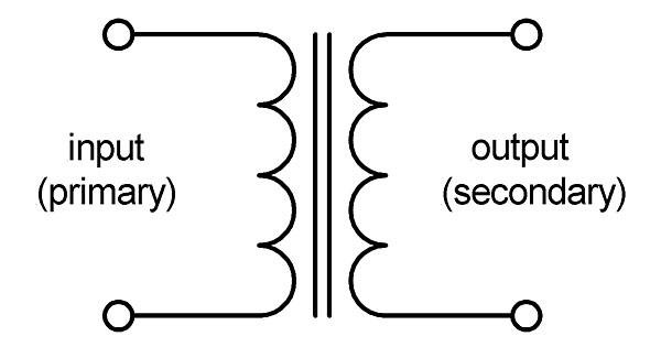
The symbol for such a transformer, in one of its simpler forms, is shown in Fig 2a. As electrical symbols go it is one of the more graphic in that the primary winding, core and secondary winding are all depicted. The twin vertical lines that represent the core indicate that in most transformers it is not a solid lump of ferromagnetic material but rather an assembly of thin laminations which are used to reduce eddy current losses.
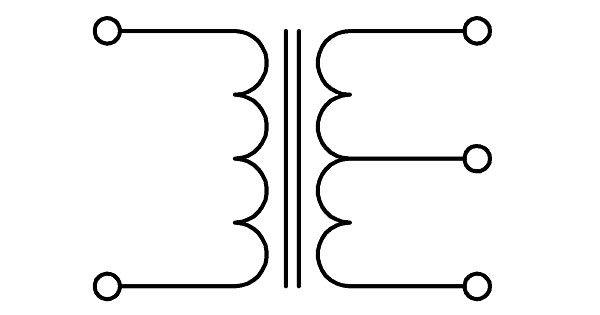
More complex transformers have further connections – known as taps – at points along the primary and/or secondary winding other than either end. Two examples are shown in Figs 2b and 2c. Fig 2b depicts a transformer with a centre-tapped secondary, ie, there's a third output connection half way along the secondary winding. Transformers of this type are commonly used in mains power supplies.
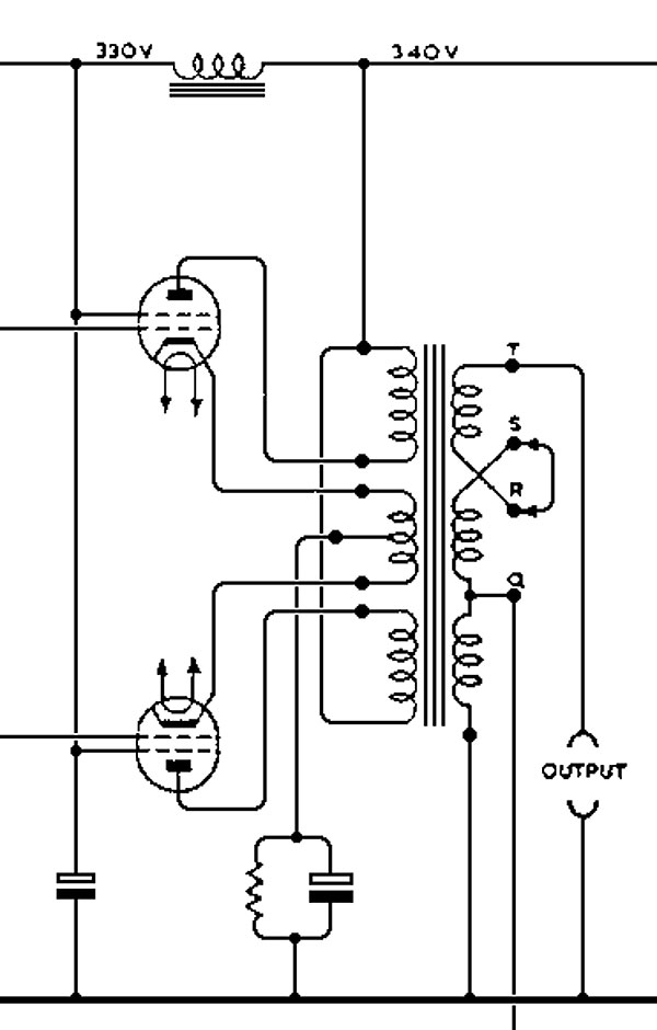
Fig 2c shows a transformer – actually, the whole output stage of the venerable Quad II – with multiple secondary windings, as was common in valve power amplifiers designed to accommodate speakers of nominally 4ohm, 8ohm or 15ohm impedance. (As 15ohm speakers are now rare, valve power amps often make do with two outputs to provide good matching with either 4 or 8ohm speakers.)
As Faraday found, a transformer conveys changes in primary current. When there is no such change, nothing happens in the secondary circuit. So transformers are AC (alternating current) devices – they do not pass DC (direct current). In a mains transformer the AC signal is the 50Hz (or 60Hz) mains waveform, while in signal transformers in audio equipment it is the audio waveform itself. Transformers are used in audio for four main purposes:
1. The stepping up or stepping down of alternating voltage.
2. Impedance matching.
3. Balanced/unbalanced conversion.
4. Galvanic isolation.
Sometimes a transformer combines more than one of these roles.
Let's begin with voltage step up/step down. In many, but by no means all, transformers the number of coil turns in the primary and secondary windings are markedly different. Let's take a simple example of a transformer with twice as many turns in its secondary winding as in its primary winding. If we apply an alternating voltage of, say, 10V across the primary then the open-circuit voltage across the secondary – in accordance with the turns ratio of 1:2 – will be twice that, or 20V.
A good example of a step-up transformer in audio is a moving-coil transformer, used to step-up the output voltage of a low-output moving-coil pick-up cartridge to a level suitable for connection to a moving-magnet phono input. A gain of 24dB (16x) is typical here, which will also step down the load 'seen' by the cartridge from the standard MM input value of 47kohm to below 200ohm (see later).
Stepping Down
More often in the transformers we encounter in audio circuits – whether they are mains transformers in the power supply or the output transformers in valve power amps – the transformer doesn't step up the voltage but steps it down instead. In other words, the primary winding has more turns than the secondary winding.
In the case of mains transformers this is because the mains voltage – nominally 230V in the UK – is much higher than the DC voltage required internally. So the mains transformer steps down the mains voltage, after which the AC waveform is rectified and smoothed to create a DC supply to power the audio circuits.
The major exception to this is mains transformers used in valve equipment, where much higher internal voltages are required than in solid-state alternatives.
|
| |||||||||


| Equipment Reviews | Music Reviews Awards | Latest News Features | Resources Newsletters | Subscriptions |
WHERE TECHNOLOGY BECOMES ENTERTAINMENT
 © 2026 Hi-Fi News
AVTech Media Ltd
All rights reserved