Yamaha C-2a/M-2 Pre/Power Amplifier
 With VFETs costing top dollar and facing stiff competition from other semiconductors, the late '70s saw Yamaha unveil a new pre/power amp duo. How does it sound today?
It's always intriguing to see how a company reacts to the realisation that a technology it has championed is reaching its sell-by date. This was the situation faced by Yamaha in the late 1970s. Since the middle of that decade, its top-end products had made use of Jun-ichi Nishizawa's Static Induction Transistor – more commonly known as the VFET – to great effect. This led to the development of designs such as the B-1 and B-2 power amplifiers, and C-1 preamplifier, all of which are still held in high regard.
Switch In Time
The problem was that only Yamaha and Sony ever leveraged this technology extensively, companies such as JVC and Sansui merely dabbling before moving on. As the end of the '70s approached, Yamaha had to deal with the fact that its amps were becoming relatively expensive to manufacture and proving troublesome in the hands of unwary service personnel.
There was a further issue too, which was that advances in silicon technology meant that the MOSFET was not only becoming more reliable but cheaper and easier to make. New iterations of these transistors boasting increasingly high switching frequencies made their use as audio output devices an obvious step, and all of the top Japanese manufacturers had now embraced this improved technology.
Come 1979, interest in Yamaha's mighty B-1 and B-2 VFET power amplifier models was fading. 'VFET' was no longer the big buzzword, having been replaced by 'high fT'. These new MOSFETs boasted an impressive 80MHz switching with dissipation up to 150W. So it was that these formed the basis of Yamaha's two new range-topping power amplifiers – the M-4 and the 200W-per-channel M-2 tested here.
In the case of the M-2's output stage, Yamaha made use of three parallel-connected Toshiba 2SC2461 n-channel devices and three 2SA1051 p-channel types. The use of three pairs of power devices offered, according to the company, improved linearity and distortion at low signal levels. In addition, their ultrasonic bandwidth promised improved linearity in the 'lower frequency' audio band.
Glam Metal
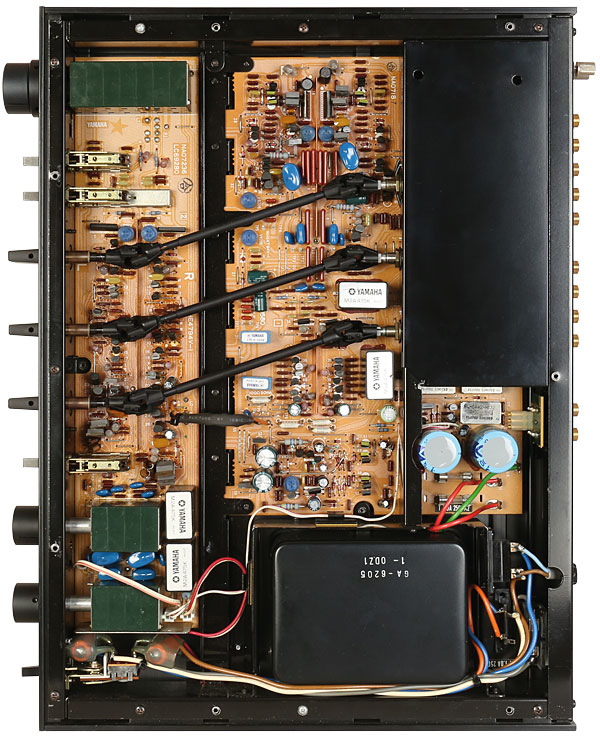
Power was provided to this output stage via a large toroidal transformer and a hefty discrete power supply. This utilised 44,000µF of capacitance and two regulated voltage supplies for each amplification stage. Meanwhile, the input amplifiers were also FET-based and saw a dual-stage topology used, the aim here being high stability and low distortion.
Apart from the two large electrolytics in the PSU, all other capacitors were either Mylar or polystyrene. Meanwhile, the amp's internal earthing bar was pure copper, giving an ultra-low impedance connection that promised 'reduced intermodulation distortion, improved separation and absolutely stable operation'.
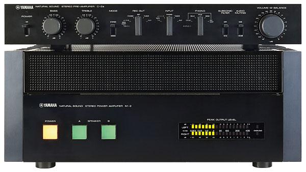
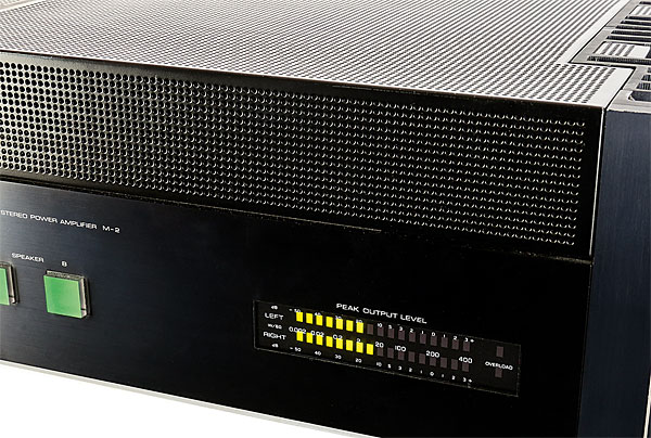
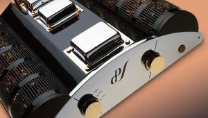
Physically, the M-2 power amp is an imposing beast. Weighing in at 21kg, each side comprises a dedicated heatsink for the output devices while the upper third of the case features a perforated metal cover, which the company hoped would recall the appearance of a classic tube amplifier.
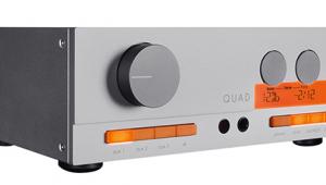
The front panel is fitted with one LED power meter for each channel, the power on/off switch, and selectors for two pairs of loudspeakers. All the switches are illuminated – power being amber and the loudspeaker selectors lighting up green.
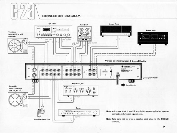
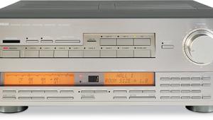
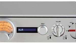
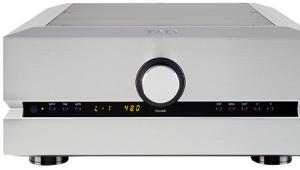
Naturally, a suitable matching preamp was required and this came in the form of the C-2a. With vinyl still the audiophile's source of choice, Yamaha spared no expense when it came to the phono stage here, utilising a dual-FET circuit with multiple stages in a bid to minimise DC drift while promising reduced distortion and an extended frequency response. In fact two phono inputs are provided, with options selected via a dedicated front panel control. Phono 2 is a fixed MM input with a standard 47kohm load, but Phono 1 could be configured for MM or MC operation. For MM, loads of 47kohm, 68kohm or 100kohm were available, while the standard MC input offered a 50ohm load. What's more, the C-2a's Phono 1 selector had a fourth option, offering a 2.5mV MM input sensitivity combined with 100ohm loading. This was intended for use with the new breed of high-output/low-ish impedance MC cartridges.
Added Value
In addition, a pair of sockets on the rear of the C-2a gave capacitive loading options for the MM Phono 1 input. With nothing connected, the load was 220pF and plugs were provided to alter this to 330pF or 470pF. The manual also gave the appropriate calculation for the user wanting to make up plugs for other values.
The rest of the C-2a was equally well specified. Both Tuner and Auxiliary inputs were offered, plus two tape loops with a separate record output control. High-precision metal film resistors and polypropylene capacitors were employed throughout while the amp's volume control was a four-gang unit unique to the model. Two of these gangs were used on the input to the amplification circuitry and two on a subsequent gain stage, with the intention that hum and noise be minimised at lower volumes.
Power to the C-2a came from a high quality, fully regulated power supply with separate sections for each amplification block within the unit. A dedicated supply was also provided for the MC head amp to minimise the effect of general power fluctuations on its sensitive circuitry.
|
| |||||||||


| Equipment Reviews | Music Reviews Awards | Latest News Features | Resources Newsletters | Subscriptions |
WHERE TECHNOLOGY BECOMES ENTERTAINMENT
 © 2026 Hi-Fi News
AVTech Media Ltd
All rights reserved