Improving Groove Contact
Carbon is one of the most common and versatile elements found on Earth. In its purest form it has the odd characteristic of being what chemists call allotropic. That is to say, it can appear in more than one distinct form of the same state.
Carbon's two main allotropic forms are diamond and graphite, each of which has unique properties of great value. Graphite can be used for pencils when moulded into thin rods with clay, it is valuable as electrodes in various chemical processes, it can be used to make crucibles, or as a lubricant. The diamond, however, is completely different in its mechanical properties and is noted not only for the great beauty of its cut crystals when used by a jeweller, but also for being the hardest substance known to man.
Hardness is a property which suggests resistance to frictional wear, and it is this factor which makes the diamond of such great interest to manufacturers of pick-up styli. Cutting, grinding and polishing diamonds for their varied applications is an extremely specialised skill found in only a few factories around the world. Most of the diamond tips used for pick-up styli are processed in Japan, with Switzerland and Germany also playing a leading role.
Crystal Maze
Designing a stylus tip also requires great skill, and an understanding of the basic crystal structure of the diamond. Typically, a well formed crystal looks like an octahedral rod, but the internal make-up of the crystal lattice – or array of atoms that make up this rod – is more complex. The structure of the lattice looks like a tight pyramid of atoms, and the way in which these pyramids interface produces a series of angles to the main surfaces of the rod, which can be easily cleaved or cut to produce the multi-faceted brilliants often used by the jeweller.
The stylus-tip designer is concerned with four principal features: (1) the final mass of the tip, (2) the hardness of the surfaces eventually placed in contact with the walls of the disc groove, (3) the geometry of these contact surfaces, and (4) the ease of manufacture. Of these, the first and the third have been the most publicised, since they seem to be more closely related to the quality of reproduction.
In recent years more light has been shed on the effects of other parameters, to show that the idealised geometry conceived by the stylus designer is often not met in practice, either because of difficulties in manufacture, or because of rapid wear producing a less than optimum shape of tip.
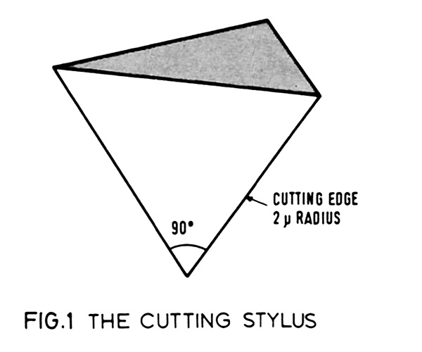
The starting point is the cutter blade that forms the original disc groove. lt is in the shape of a pointed chisel [see Fig 1] in which the actual cutting edges are rounded to a radius of about two microns. The included angle of the groove when unmodulated is about 90o, although this can reduce to as little as 60o with heavy modulation (if one views the groove across the modulation waveform at its steepest points instead of at right angles to the mean groove path).
Because the disc rotates at a constant radial velocity, the actual linear velocity of the disc beneath the cutter varies from the outer to the inner grooves. This means that the physical wavelength of a pure tone recorded at the outer and inner grooves will be different. The shortest wavelength will be found at the innermost groove. For example, a half-cycle at 15kHz will occupy only about seven microns at a radius of 6cm (the approximate minimum radius of a record groove), but at the maximum radius of about 14.5cm will occupy about 16.6 microns.
Land Ahoy!
The actual minimum radius of curvature at the modulation waveform crests due to a 15kHz signal will depend also on the amount of sideways excursion of the cutter, and at such a high frequency this is bound to be small. For the purpose of this simple discussion, however, we shall assume that the smallest radius of modulation that the stylus has to trace accurately will be about seven microns.
Two other factors of groove geometry are important. During cutting, the material chiselled from the groove is normally completely removed, but at the same time a certain amount is displaced or squeezed up to form 'lands' at the top edge of the groove. Should a stylus be of large enough radius to ride on these lands then distortion is bound to occur, since the amount of material found at this point will be variable. The second factor concerns the bottom of the groove, which tends to accumulate rubbish of all sorts. Again, if the stylus design permits the tip to explore this part of the groove, reproduction will be marred by extraneous noise.
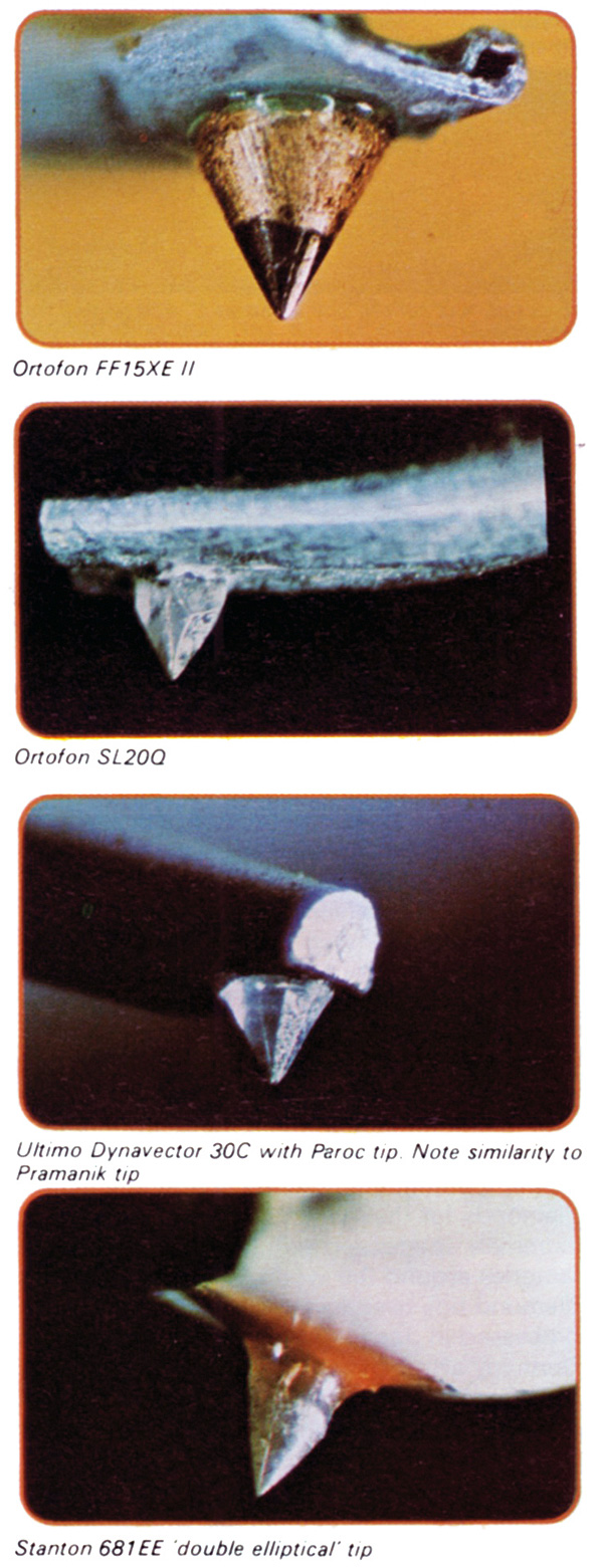
Early stylus tips were usually designed as truncated cones having an included angle of about 55o rounded off at the tip into a ball having a radius, for microgroove LPs, of typically between 12.5 to 25 microns. Clearly, when compared with the figure given for the half wavelength of a 15kHz signal at the smallest disc diameter, the 12 micron tip is unable to trace the recorded signal, while larger diameters will skate across such modulations.
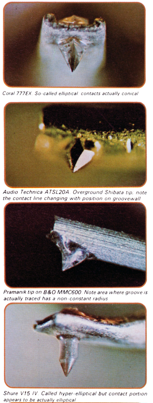
Body Double
This led eventually to the development of the elliptical or bi-radial stylus which, if viewed at the point of contact with the groove, clearly shows two radii. The smaller of these can vary from five to ten microns, which suggests that the elliptical profile should at least be capable of inserting its radius within our crucial seven microns (representing the smallest audio signal wavelength). Nevertheless it still may not trace the equivalent waveform motion with absolute accuracy.
Finally, a further development occurred with the advent of quadraphonic discs, and in particular the CD-4 type which required that the stylus should scan frequencies well above 20kHz to detect the special carrier signals without wiping the modulations from the groove. Thus appeared the Shibata tip and several others of similar design. Their virtues have been further explored with the adoption of the long-contact profile.
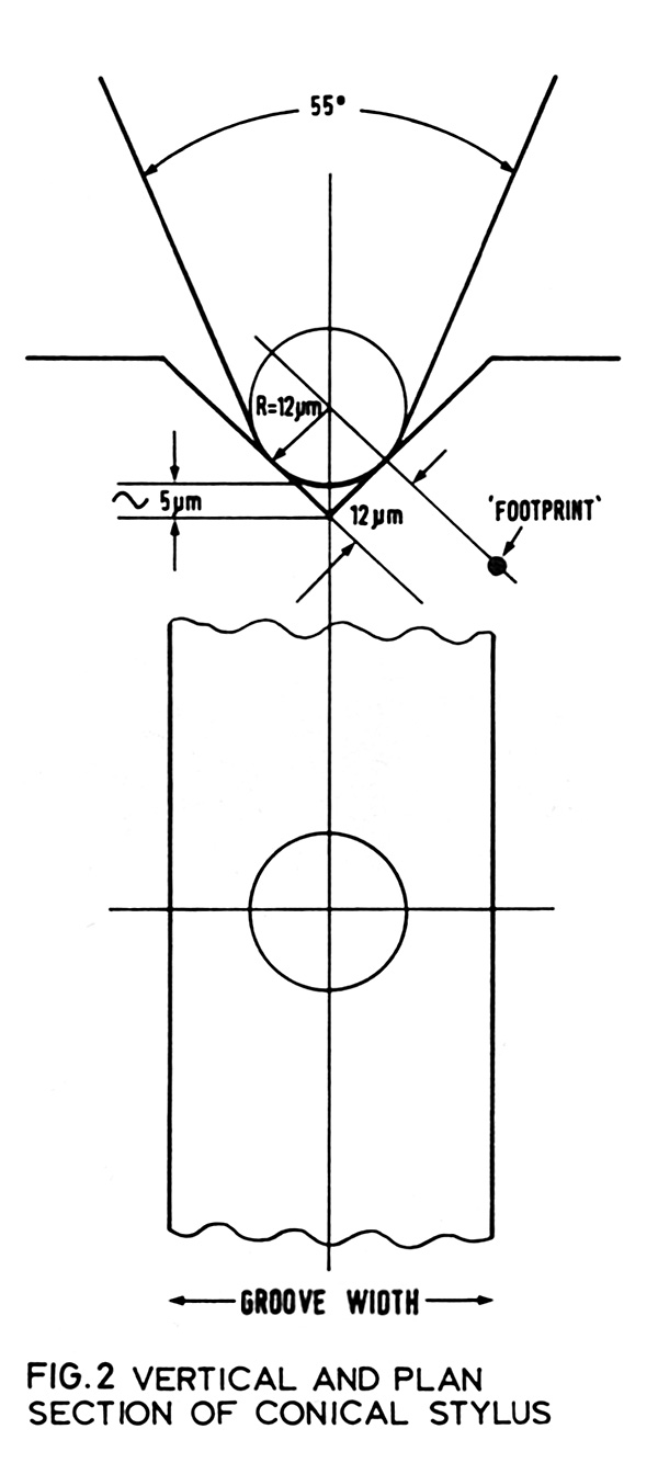
High Risk
To go back to the spherical tip for a moment, referring to Fig 2 it can be seen that each of the two contact areas will be at a point – or at least a small disc due to indentation of the vinyl. The only situation in which this shape tends to change is when the radius of the groove modulation approaches that of the tip, in which case the contact approximates to a line parallel to the groove wall. This only happens precisely when the radius of the tip exactly fits the radius of modulation.
|
| |||||||||


| Equipment Reviews | Music Reviews Awards | Latest News Features | Resources Newsletters | Subscriptions |
WHERE TECHNOLOGY BECOMES ENTERTAINMENT
 © 2026 Hi-Fi News
AVTech Media Ltd
All rights reserved